
How to Choose a Motorized Ball Valve Wiring Type
Motorized ball valves are available with several wiring configurations. The wire count alone does not tell you how a valve behaves: some models automatically return to a preset position, some reverse direction when DC polarity changes, and others accept a controller signal or provide position indication.
This guide follows the wiring-type collections available in our store. Use it to compare the listed configurations, match them to your controller and application, and identify what to confirm on the exact product page before ordering.
Wiring Types in Our Motorized Ball Valve Collections
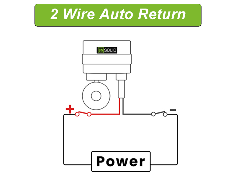
1. 2 Wire Auto Return
Motorized ball valves with the two wire auto return function can be vital in some applications. They are often used as a backup shutoff valve for water systems. When power is removed, the valve automatically closes. This does mean the valve uses nominal energy even when fully actuated, as it has to be able to close at power shutoff. These valves can be connected to a simple on/off switch for a hassle-free setup and start.
2. 2 Wire Reverse Polarity
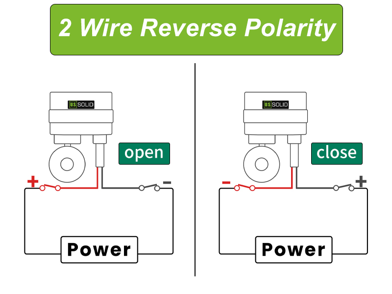
The 2 wire reverse polarity motorized ball valves are easy to use, and quick to setup. They use no energy once fully opened or closed, which can be important in systems with limited power (sailboats, for example). One of the most popular ways this ball valve is employed is using a Double Pole Double Throw Switch (DPDT). This allows to open or close the valve at the simple flick of a switch.
3. 3 Wire (1 Point Control)
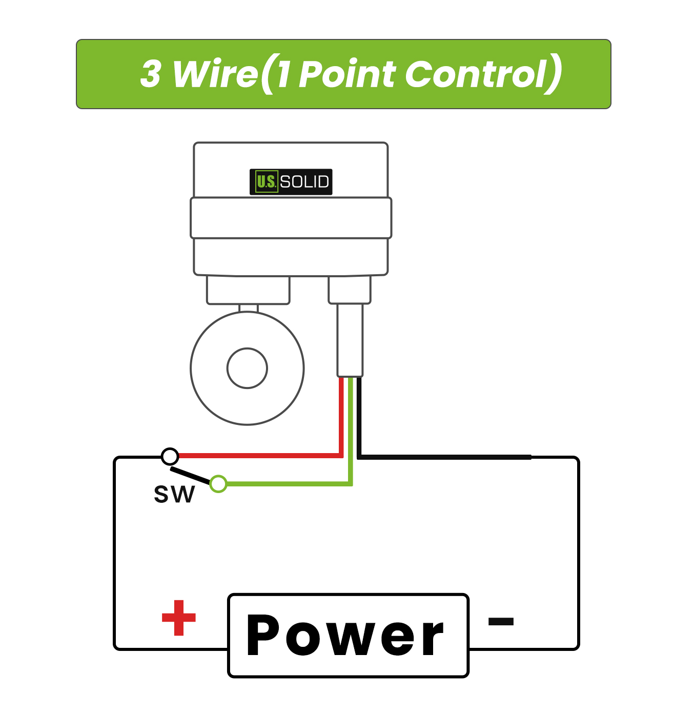
The three wire one point control motorized ball valve is opened and closed from a single control point. Two of the wires stay connected to power, and the third is the control wire: energizing it drives the valve to one position, and removing the signal drives it back to the other. A simple single pole switch, thermostat, timer or one relay output on a PLC is all it takes to operate the valve, with no polarity reversing and no second control circuit required. The actuator shuts off once the valve is fully open or closed, so it uses virtually no energy while holding position. Wiring is straightforward and setup is quick, which keeps installation and maintenance costs down. We offer the 3 wire one point control model in many different sizes, in brass, stainless steel, UPVC and CPVC.
4. 3 Wire (2 Point Control)
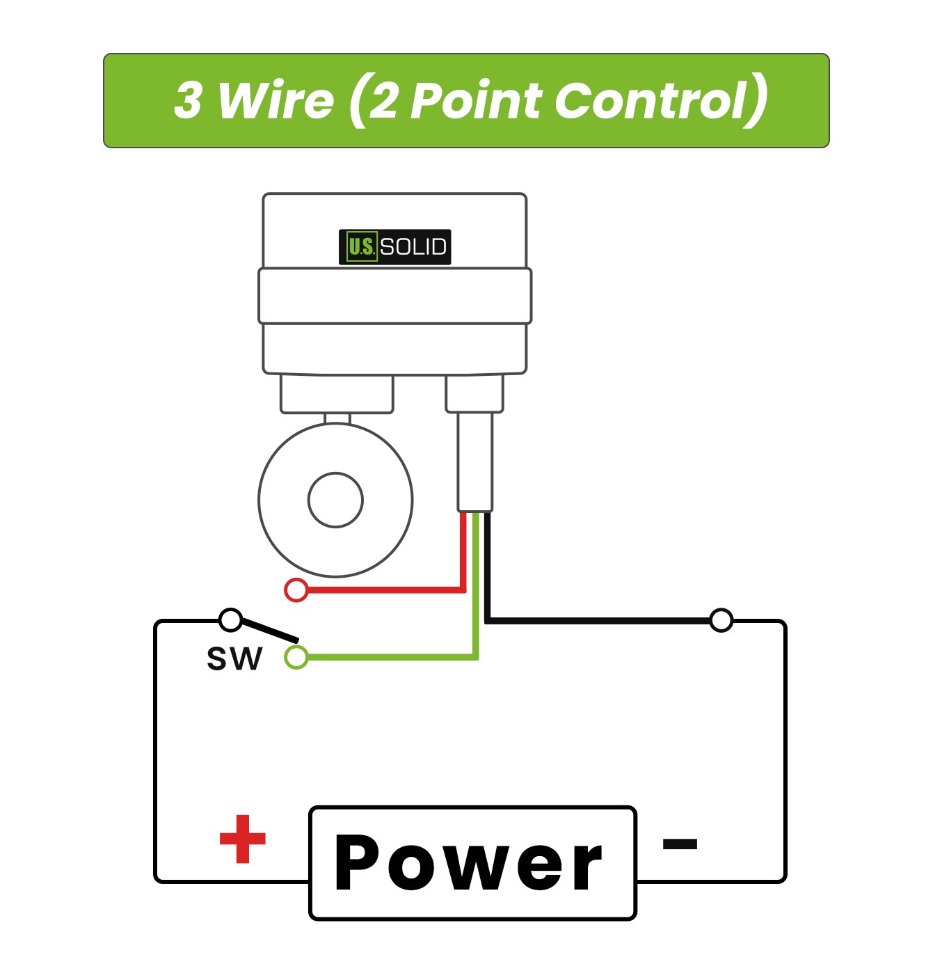
The three wire model of motorized ball valves offers a unique level of control. Specifically, it offers two point control. For more complicated systems, automated systems, or someone who wants those options in the future, the 3 wire two point control system is the right choice. We offer the three wire model in many different sizes, in stainless steel, brass, UPVC and CPVC.
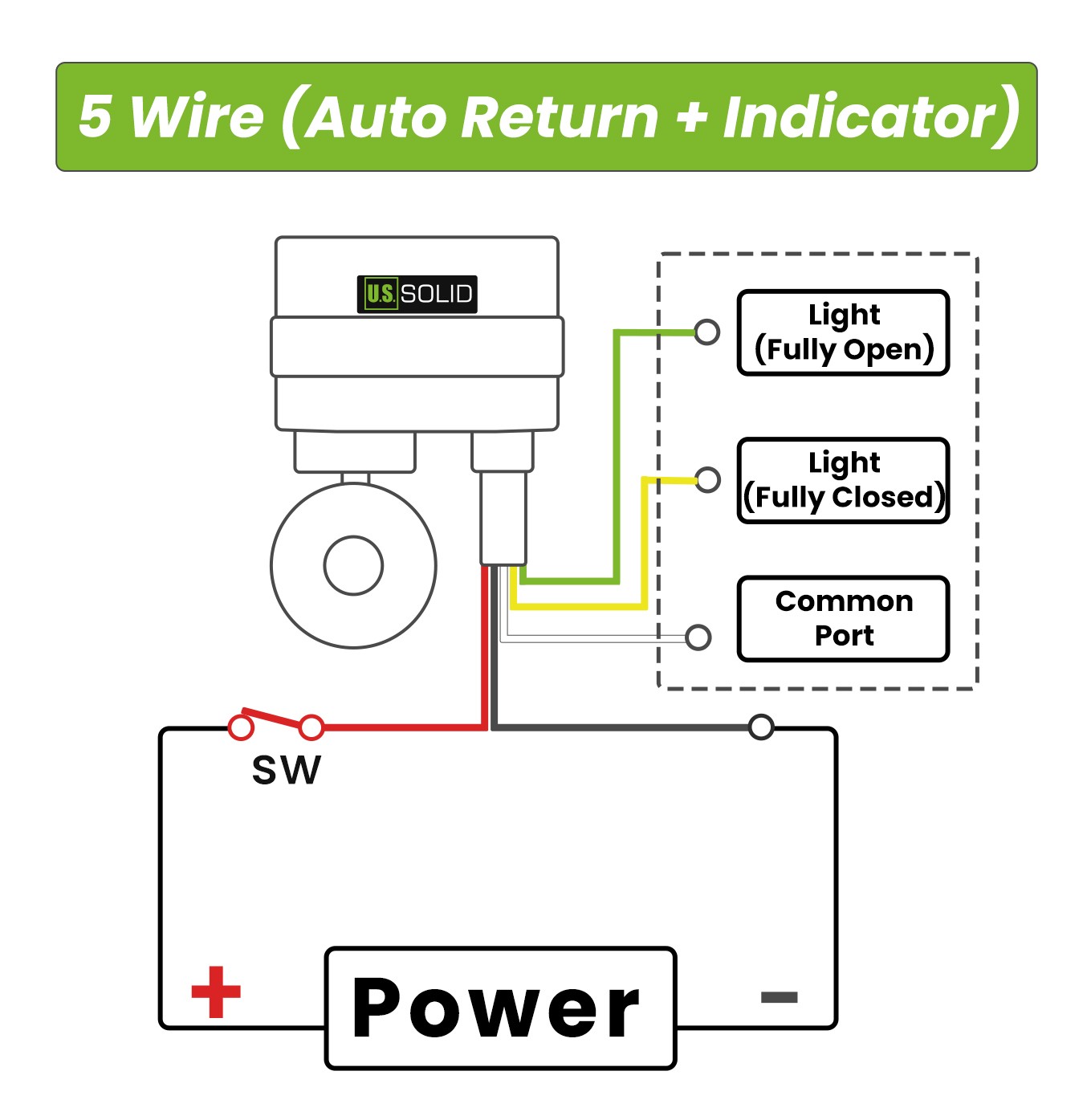
5. 5 Wire (Auto Return + Indicator)
The five wire motorized ball valve model is the right choice if you need indicator lights. It comes ready to wire for lights that will visually show whether the valve is open or closed. In many automation systems, this is critical, as operators must be able to readily tell the status of the different components. This 5 wire electrical ball valve comes in several different sizes, in both brass and stainless steel.
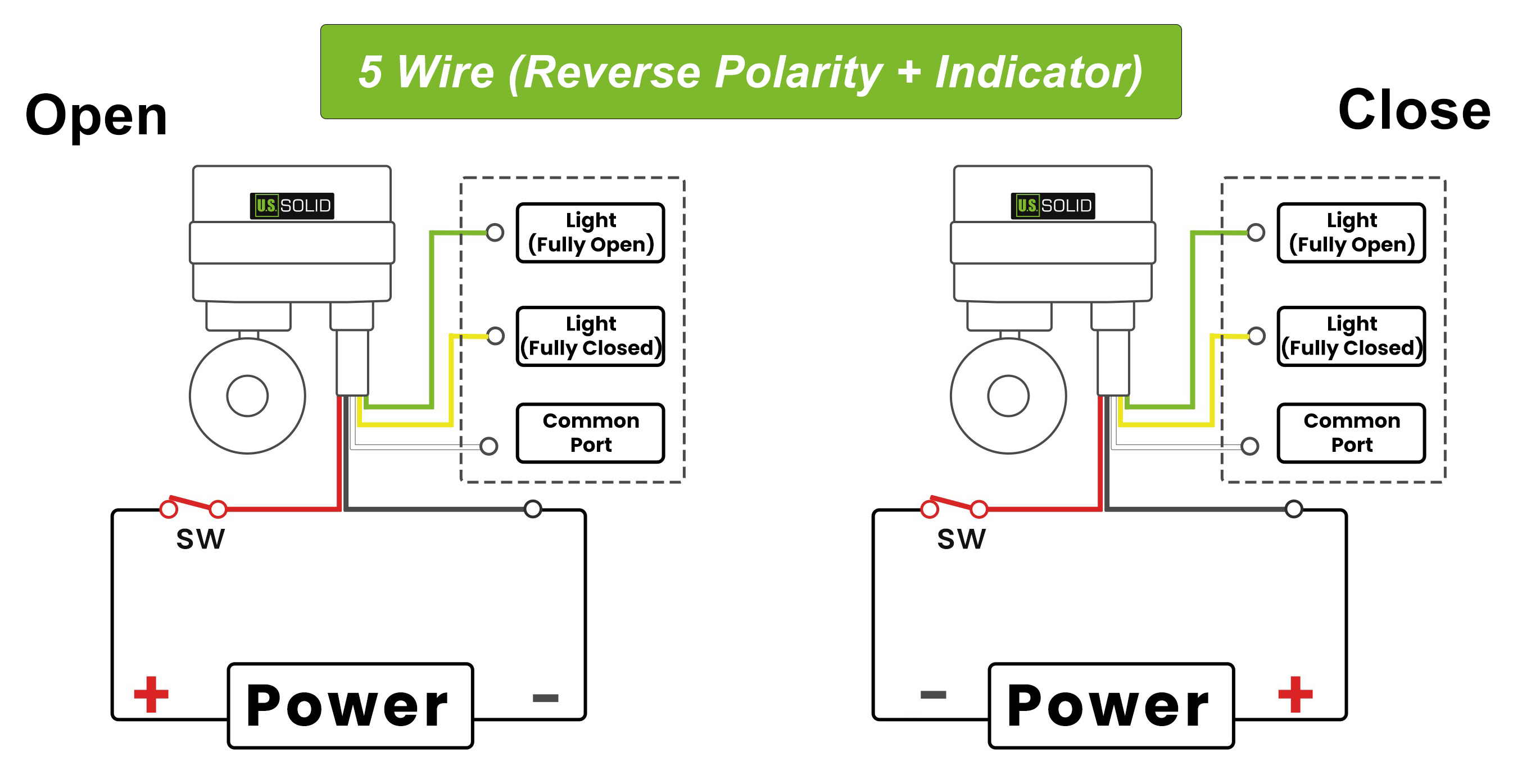
6. 5 Wire (Reverse Polarity + Indicator)
The five wire reverse polarity motorized ball valve pairs our 2 wire reverse polarity wiring with indicator lights. The control side is easy to use and quick to set up, and uses no energy once the valve is fully opened or closed, which can be important in systems with limited power (sailboats, for example). One of the most popular ways this valve is employed is with a Double Pole Double Throw (DPDT) switch, which opens or closes the valve at the simple flick of a switch. The remaining wires come ready to wire for lights that will visually show whether the valve is open or closed, so operators can readily tell the status of the different components. This 5 wire electrical ball valve comes in several different sizes, in both brass and stainless steel.
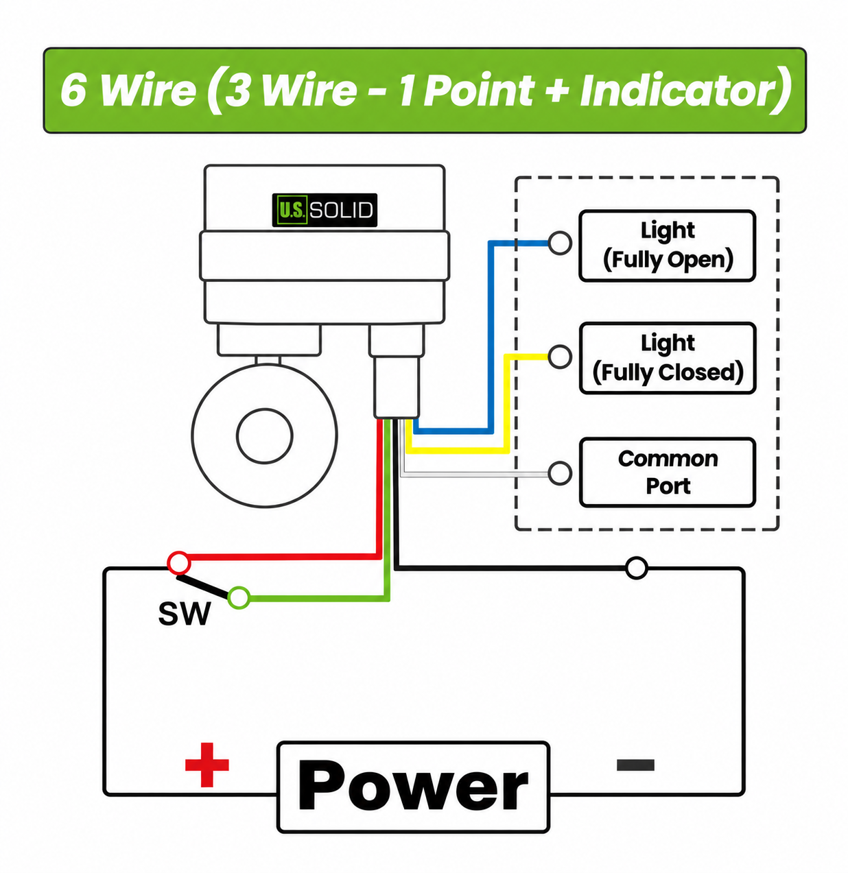
7. 6 Wire (3 Wire - 1 Point + Indicator)
The six wire motorized ball valve is our 3 wire one point control model with a dedicated indicator circuit added. Three wires handle the control side, opening and closing the valve from a single control point with quick response and high precision, while the other three wires are ready to wire for indicator lights that visually show whether the valve is open or closed. In many automation systems this is critical, as operators must be able to readily tell the status of the different components. Wiring is straightforward, with no complex setup or debugging required, which keeps installation and maintenance costs down. This 6 wire electrical ball valve comes in several different sizes, in both brass and stainless steel.
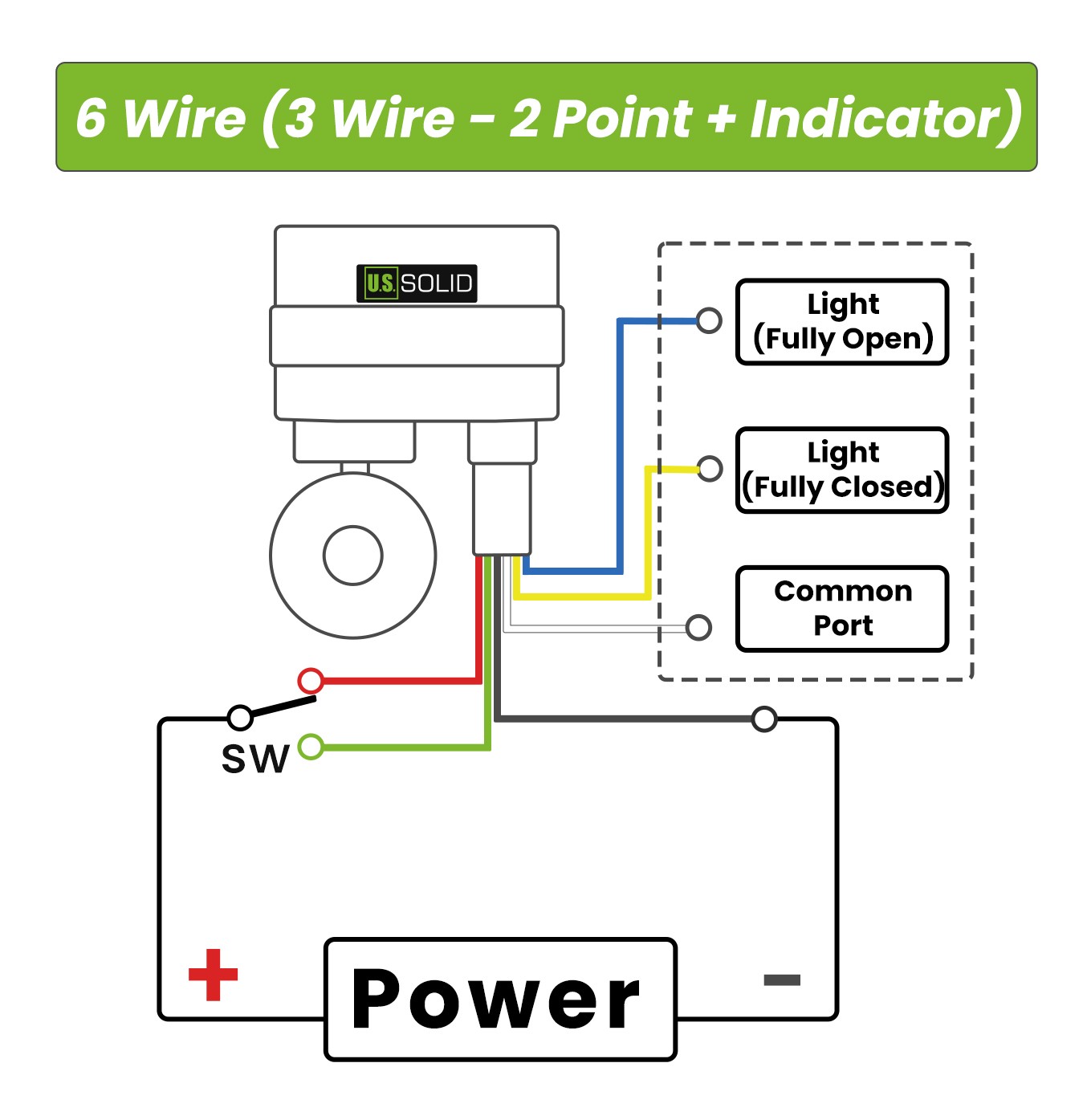
8. 6 Wire (3 Wire - 2 Point + Indicator)
The six wire motorized ball valve is our 3 wire two point control model with a dedicated indicator circuit added. Three wires handle the control side, offering the unique two points of control that suit more complicated or fully automated systems, while the other three wires are ready to wire for indicator lights that visually show whether the valve is open or closed. In many automation systems this is critical, as operators must be able to readily tell the status of the different components. For someone building a larger system, or who wants those options in the future, the 6 wire two point control model is the right choice. This 6 wire electrical ball valve comes in several different sizes, in both brass and stainless steel.
Compare the Collection Types
| Collection wiring type | What distinguishes it | Consider it when | Confirm before ordering |
|---|---|---|---|
| 2 Wire Auto Return | Automatically closes when power is removed; the collection notes nominal energy use while actuated | You need a water-system backup shutoff | Exact model, supply, and auto-return behavior |
| 2 Wire Reverse Polarity | DC direction changes when polarity is reversed | Your controller supports polarity reversal | DC rating and controller output compatibility |
| 3 Wire (1 Point Control) | Single control point; third wire switches valve position, and the actuator shuts off at the end position | You need automated, responsive open/close control | Resolve the control-point arrangement using the model diagram |
| 3 Wire (2 Point Control) | Uses the collection's two-point control arrangement | Your controller provides the matching commands | Common lead, command inputs, and interlocking |
| 5 Wire (Auto Return + Indicator) | Collection description specifies lights that visually show open/closed status | Operators need a visual valve-status indication | Power-loss return behavior and indicator connection |
| 5 Wire (Reverse Polarity + Indicator) | Reverse-polarity control plus indicator wiring | You need DC direction control and status indication | Polarity logic and indicator/feedback rating |
| 6 Wire (3 Wire - 1 Point + Indicator) | One-point control with added indicator wiring | Your controller matches the one-point logic and needs status | Purpose and rating of the added leads |
| 6 Wire (3 Wire - 2 Point + Indicator) | Two-point control with added indicator wiring | You need separate commands plus status indication | Two-point logic and indicator/feedback rating |
How to Choose: Five Questions to Ask
- What should happen if power is lost? The 2 Wire Auto Return collection says the valve closes when power is removed. For other types, check the exact model’s behavior rather than assuming it will return or stay in place.
- What outputs does your controller provide? Match it to the exact collection type: reverse-polarity DC, 1 Point Control, 2 Point Control, or the model-specific two-wire logic.
- Do you need an indicator or feedback? Compare the 5-wire and 6-wire indicator collections, then verify whether they provide local indication or an electrical signal your controller can read.
- Does the electrical supply match? Confirm the valve's exact voltage and AC/DC rating. A wiring layout does not make a valve compatible with a different supply.
- Will the application use two-way shutoff or three-way flow switching? For a three-way valve, check its port diagram and flow path as well as the wiring. The wiring type alone does not define which ports connect in each position.
Choose by Application
- Automatic leak shutoff: Consider an auto-return valve that returns closed, then confirm the model's default position and return behavior.
- Water-system backup shutoff: Consider 2 Wire Auto Return, which the collection describes as closing when power is removed. If visual status is needed, review the 5 Wire (Auto Return + Indicator) product details and confirm its return behavior.
- DC controller with direction switching: Consider 2 Wire Reverse Polarity or 5 Wire (Reverse Polarity + Indicator), depending on whether indication is needed.
- Panel control: Compare 3 Wire (1 Point Control) with 3 Wire (2 Point Control) against the controller's actual outputs. Add the matching 6-wire indicator version if position status is also needed.
Final Checklist
Before ordering, write down the supply voltage, AC or DC, exact wiring collection type, controller output, desired behavior during power loss, need for an indicator or feedback, valve port configuration, and connection size. Then compare those requirements with the product's wiring diagram—not just the number of wires.
You can also browse our motorized ball valves and check each product page for its wiring type and manual.