


Problem 1: Basic Principle
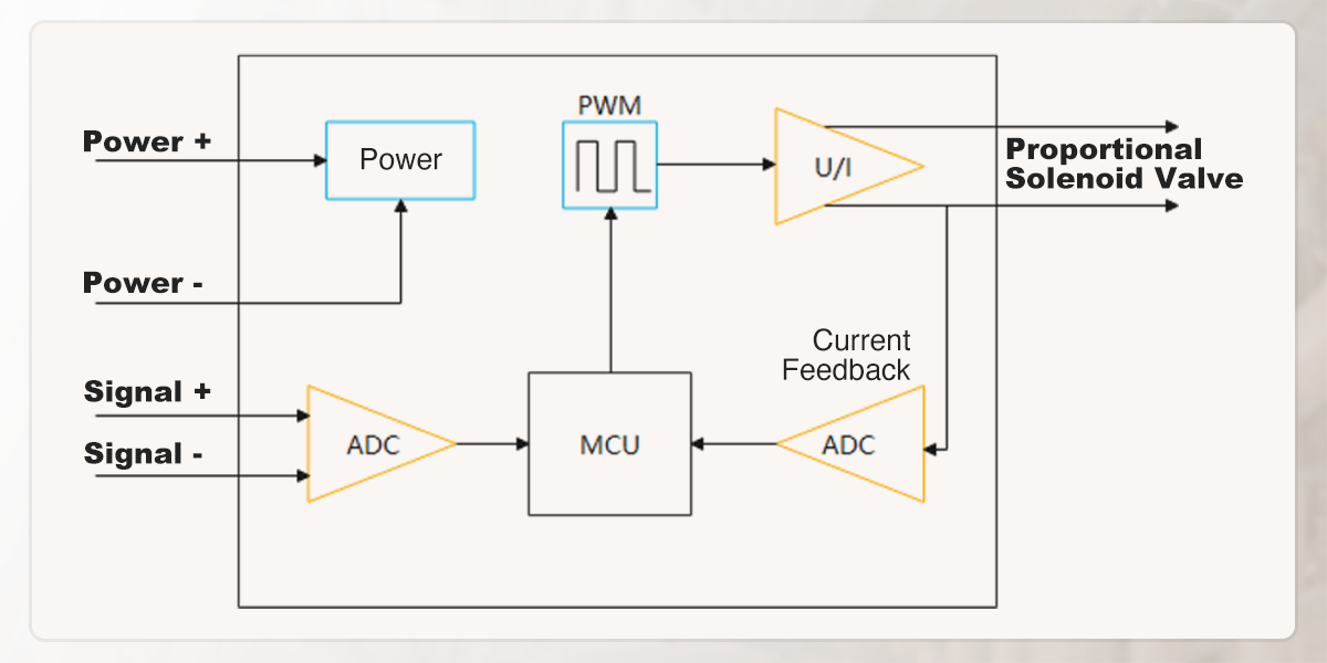
The controller is driven by standard industrial field signals, where its core function is to convert these commands into high-frequency PWM (Pulse Width Modulation) signals to proportionally regulate the solenoid's driving current. For example, if a controller has a 0-5V input and a maximum 1A output, a detected 4V signal (80% of range) will trigger the controller to modulate the PWM duty cycle to deliver an equivalent 0.8A current (80% of range) to the proportional valve.
Our controllers are signal-specific and not universal; you must select the dedicated model matching your input type (0-5V, 0-10V, 0-20mA, 4-20mA, or PWM) when ordering.

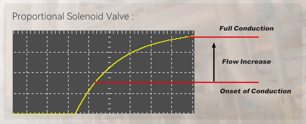
Problem 2: Common Solenoid Valve vs. Proportional Solenoid Valve
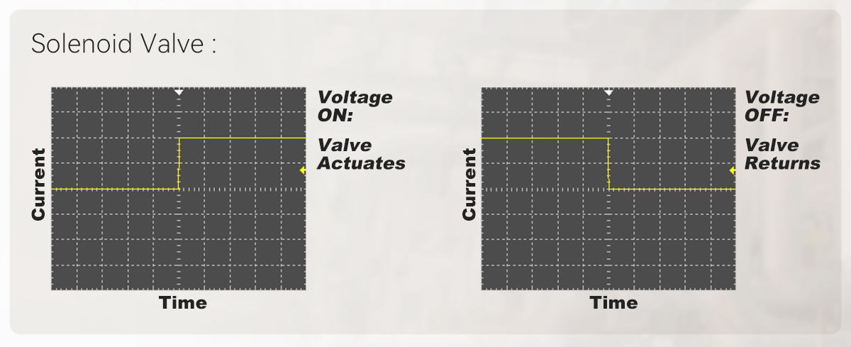
Conventional solenoids provide only ON/OFF (full flow or no flow) switching, whereas proportional solenoids allow for continuous and precise regulation of flow or pressure based on the command signal.
| Type | Function | Control Methods | ||||
| Solenoid Valve | Only has two states (open/closed), presenting as on and off externally. | Activates when powered on; stops when power is cut off. | ||||
| Proportional Valve | Can continuously and proportionally adjust opening, and control fluid pressure and flow. | Controls the proportional valve's opening via continuously adjustable current. | ||||

Problem 3: How to Use the Controller
Since conventional industrial equipment only provides a fixed voltage source (e.g., 24V DC) and no adjustable current source, a proportional valve controller is required when using the proportional valve, or you can design a dedicated proportional valve control circuit yourself to supply a stable driving current to the valve.
If you purchased our brand of proportional solenoid valve, you can buy our matching controller as needed. If you intend to use this controller with a proportional valve of another brand you already have, we do not recommend such usage.
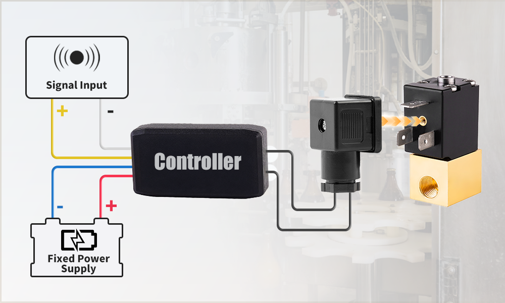
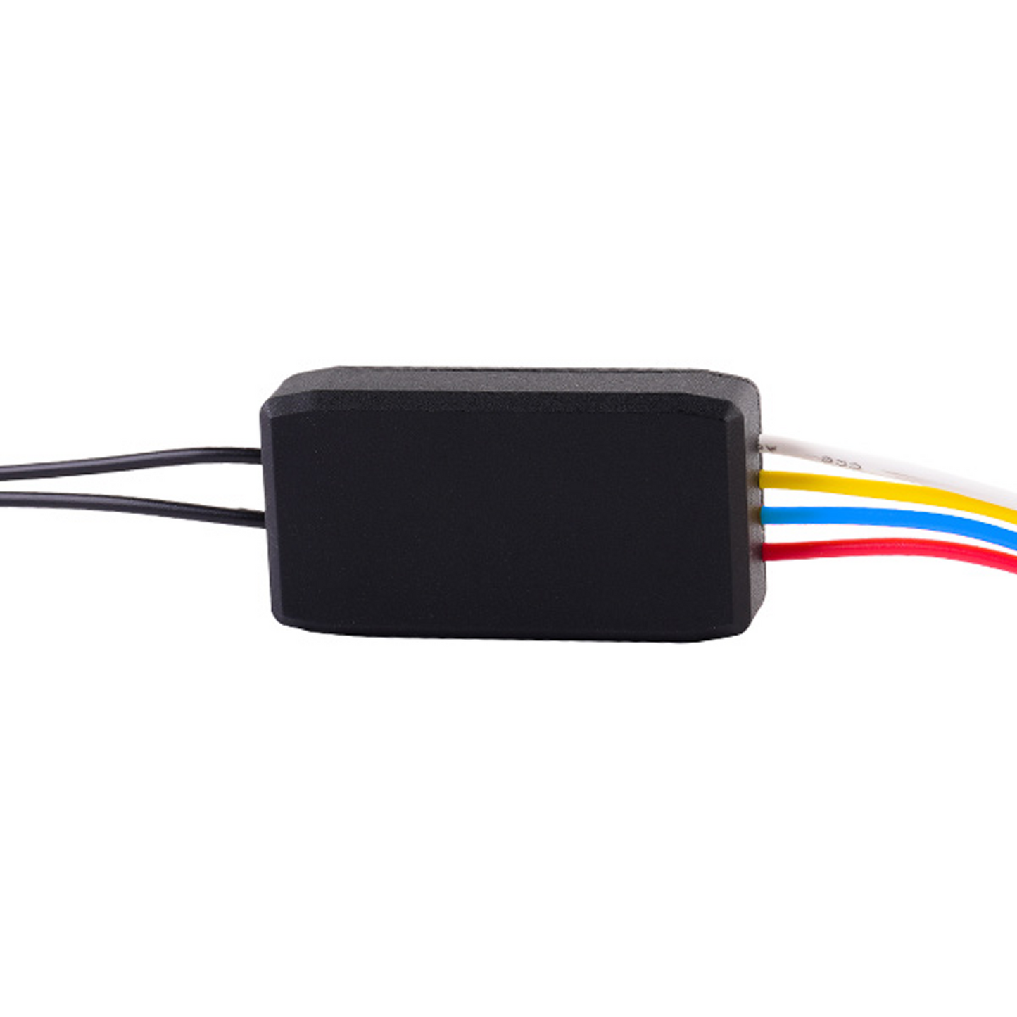
How to Use the U.S. Solid Brand Controller
- Two black leads connect to the valve (the leads are connected to the junction box, which is then connected to the valve).
- The red (positive power supply) and blue (negative power supply) leads connect to a fixed power source.
- The white (positive signal) and yellow (negative signal) leads are used to connect the input signal.
- Whether pairing with our proportional valve or using with other brands, consult customer service before purchasing the controller.
Problem 4: Other Questions
The controller is a critical component for using proportional valves. Whether purchasing it to match our valves or to work with your non-brand valves, ensure full understanding before ordering. For non-brand valve compatibility, consult customer service in advance to avoid mismatches.