INTRODUCTION
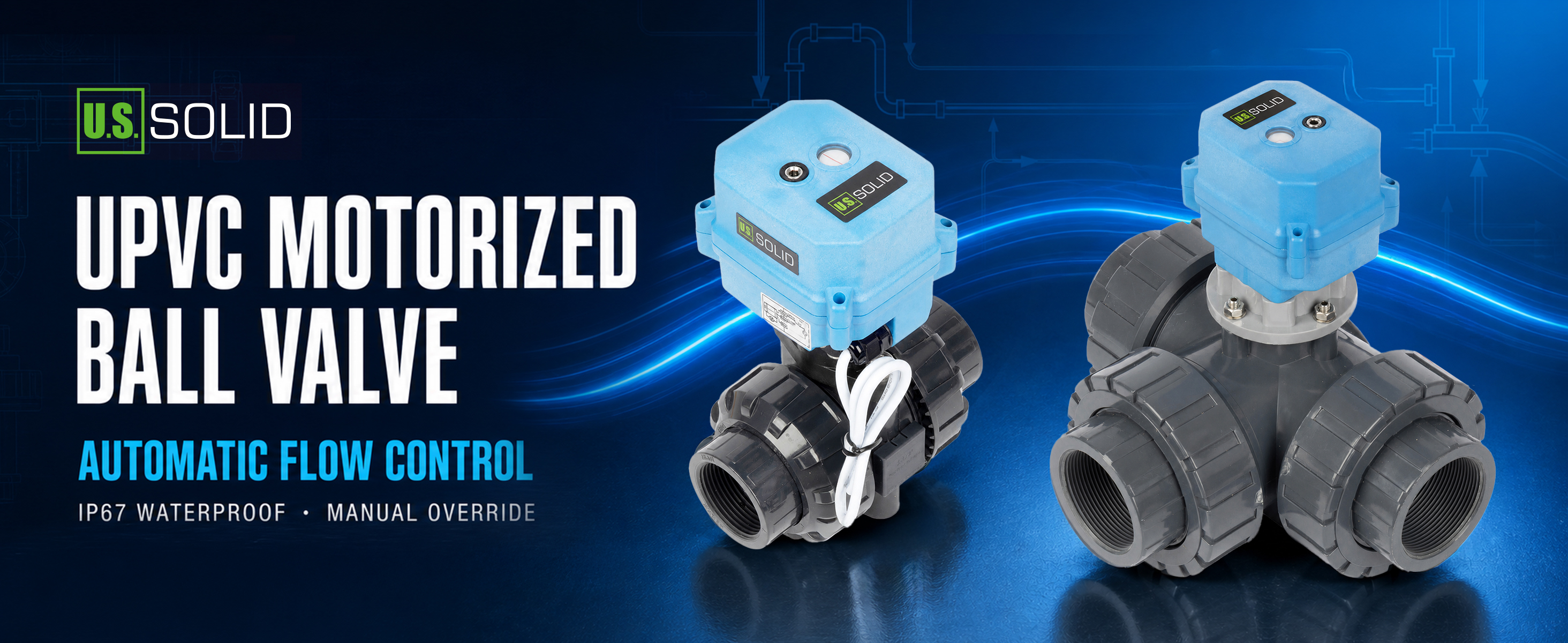
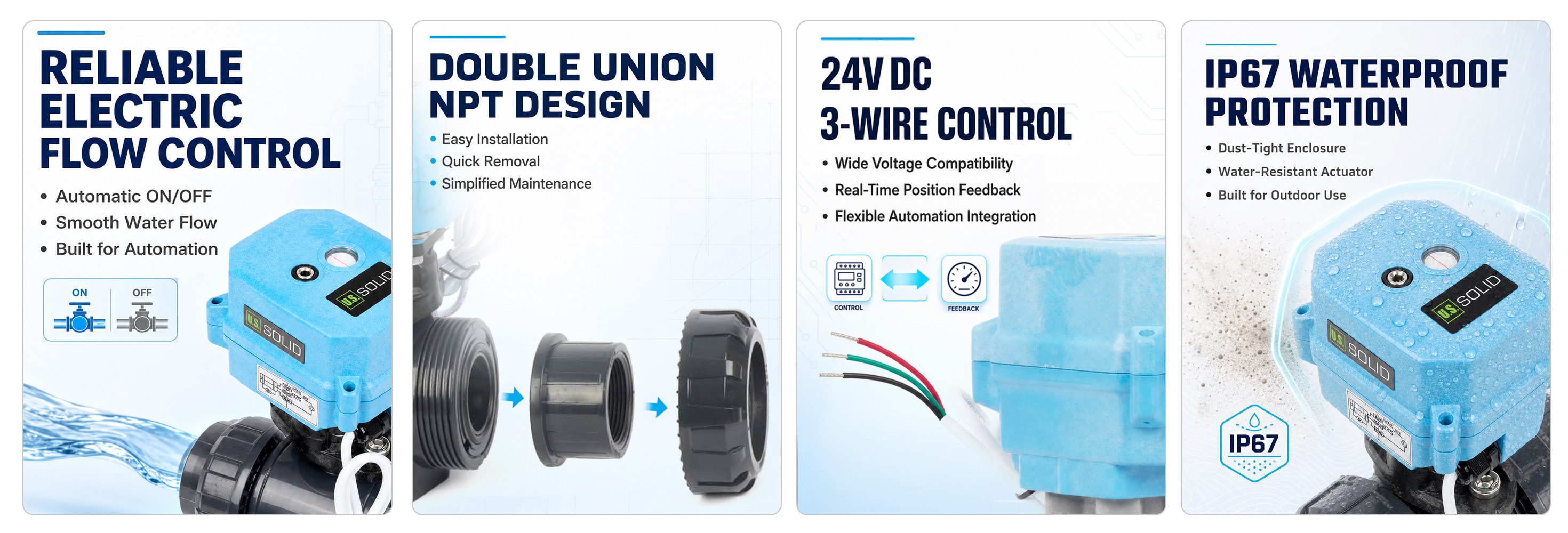
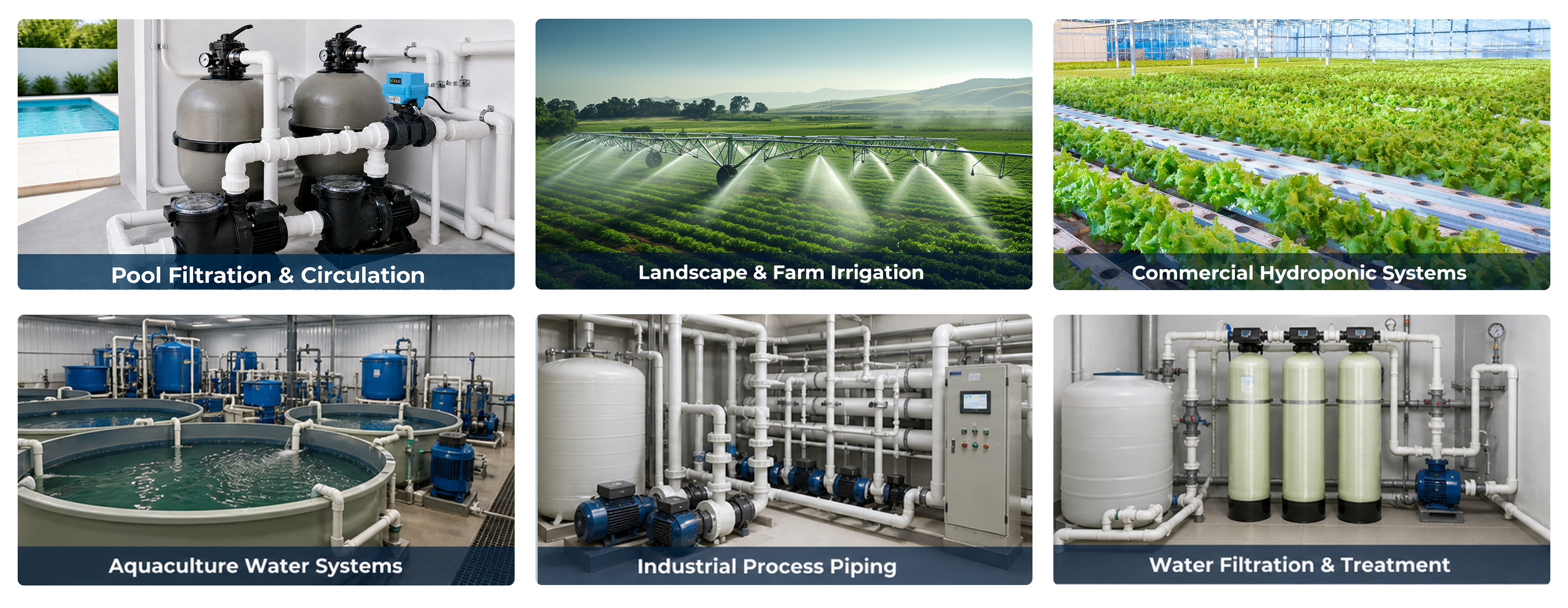
U.S. Solid UPVC Motorized Ball Valve offers reliable automatic flow control with 2-way and 3-way configurations, multiple sizes, voltage options, and wiring methods. Built with corrosion-resistant UPVC material, IP67 waterproof electric actuator, full port design, and manual override capability, this valve ensures smooth operation and easy maintenance. Ideal for pool plumbing, water treatment, irrigation, and industrial piping systems. Engineered for durability with up to 70,000 cycles of reliable performance, providing long service life and dependable flow control in demanding environments.
FEATURES
APPLICATIONS
SPECIFICATIONS
| Model | USS-MSV50307 | Brand | U.S. Solid |
|---|---|---|---|
| Port Size | 1 1/2" | Valve Material | UPVC |
| Working Voltage | DC 24V | Ambient Temperature | -15 ~ 50 °C |
| Media Temperature | 2 ~ 55 °C | IP Grade | IP67 |
| Open/Close Time | ≤ 12 s | Max Power | 36 W |
| Max Working Pressure | ≤ 10 bar | Wiring Type | 3 Wire |
| Port Type | Standard Port | Thread Type | NPT |
| Default State | None | Manual Override | Yes |
| Auto Return | No | Compatible Media | Air, Water |
| Signal Indicator | Yes | O-ring Material | EPDM |
| Service Life | 70,000 cycles | Valve Seat Material | PTFE |
| Flow Aperture | 38 mm | Max Torque | 15 Nm |
WIRING INSTRUCTIONS
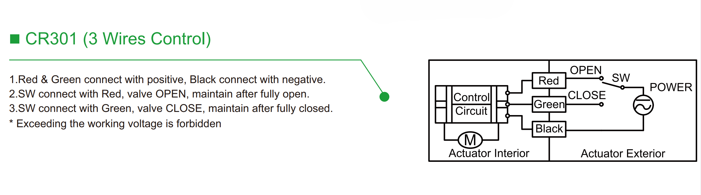
Connect the black wire to the negative or common terminal, connect the positive supply to the separate open and close control circuits, and use the changeover switch SW to select the required direction. When SW connects the positive supply to the red wire, the actuator runs toward the open position; when SW connects the positive supply to the green wire, the actuator runs toward the closed position. After the valve reaches the fully open or fully closed position, maintain the corresponding control state until the internal limit switch stops the motor. The red and green control circuits must be interlocked and must never be energized at the same time.
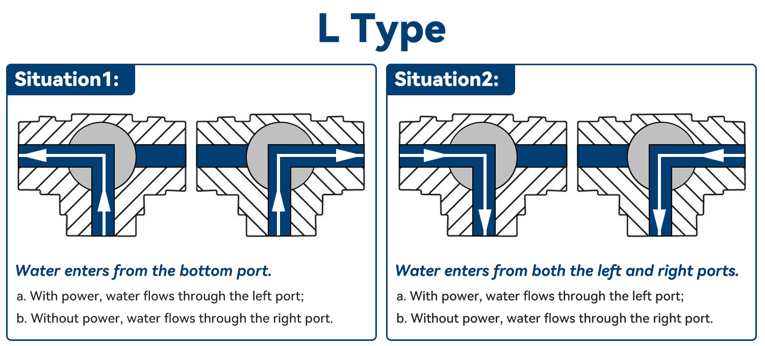
THREE-WAY FLOW DIRECTION