


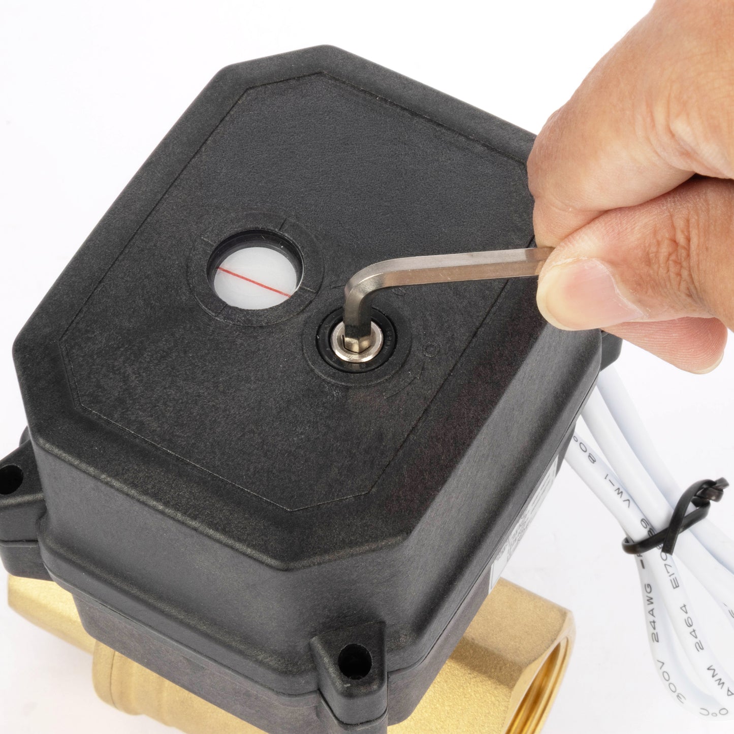
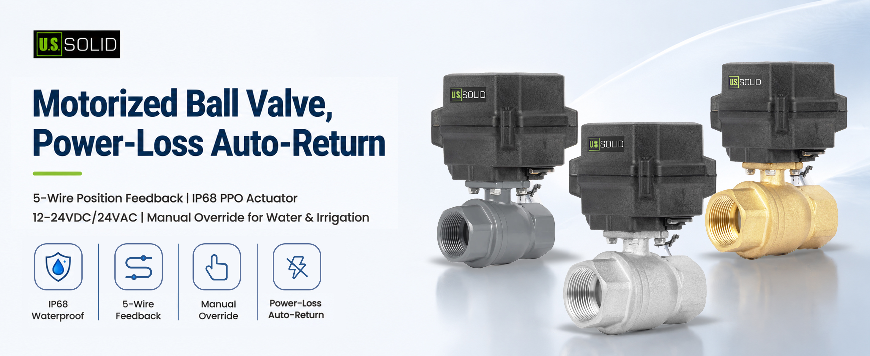
INTRODUCTION
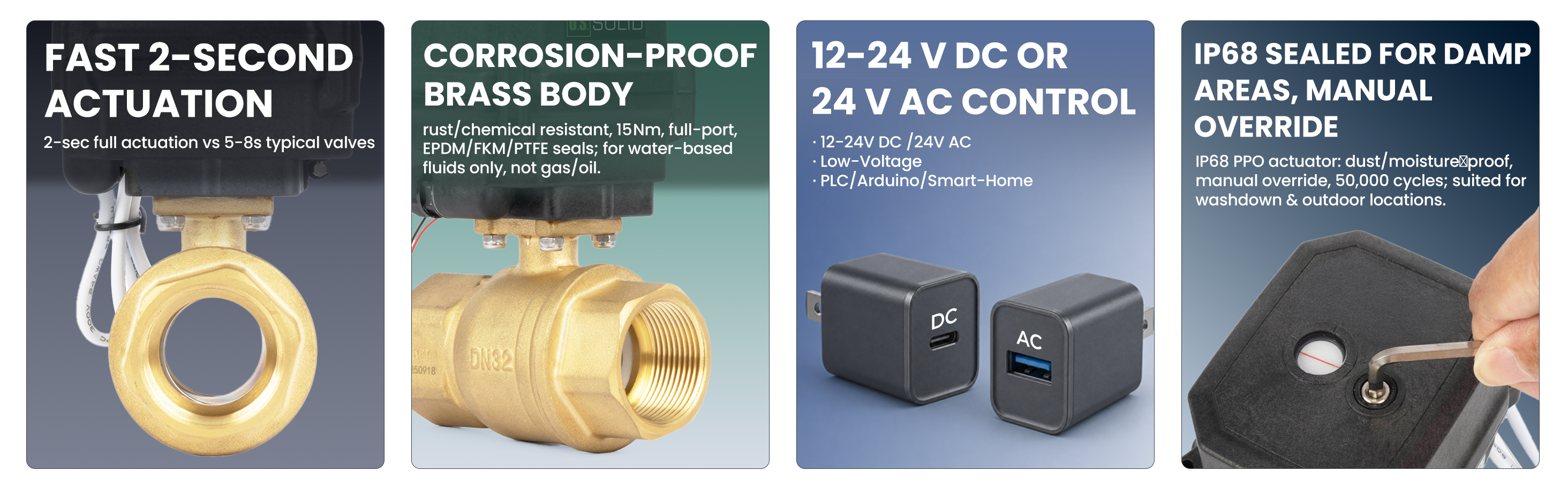
This U.S. Solid 2 in brass motorized ball valve drives fully open or closed in about 2 seconds for fast, responsive flow control. It energizes to close and auto-returns to the fully open position when power is lost, so flow stays on by default, while the 5-wire design sends open and closed signals to your PLC, controller, or panel. The high-torque brass body suits water, air, gas, and oil in HVAC, irrigation, compressed-air, and general shutoff lines. Please note the brass contains lead and is not for drinking water. The IP68 PPO actuator runs on 24V DC and includes a manual override for power outages.
FEATURES
APPLICATIONS

SPECIFICATIONS
| Model | JFMSV90003 | Port Size | 2 in NPT |
|---|---|---|---|
| Valve Material | Brass | Open/Close Time | 2 s or less |
| Working Voltage | 24V DC | Max Power | 12 W |
| Max Torque | 15 Nm | Orifice | 50mm |
| Max Working Pressure | 1.0 MPa (145 psi) | Ambient Temperature | -15°C to 50°C (5°F to 122°F) |
| Media Temperature | 2°C to 90°C (36°F to 194°F) | Service Life | 50,000 cycles |
| Default State | Normally Open | Wiring Type | 5-Wire Auto Return |
| Manual Override | Yes | Waterproof Rating | IP68 |
| Seals | EPDM, FKM, PTFE | Actuator | PPO engineering plastic |
DIMENSIONS
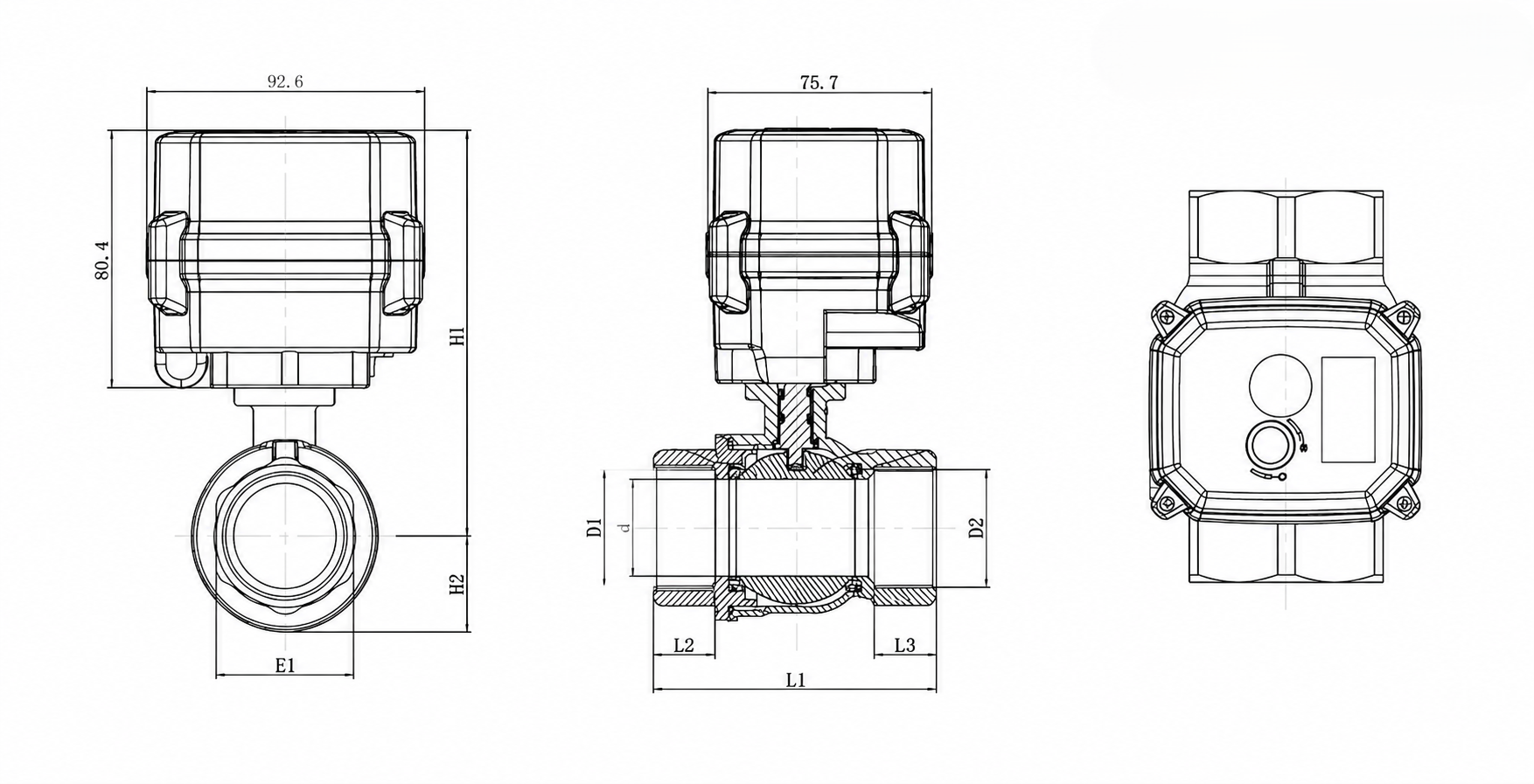
The following dimensions apply to model JFMSV90003. All dimensions are in mm unless otherwise specified.
| Model | JFMSV90003 | Material | Brass |
|---|---|---|---|
| D1/D2 | 2" | d ± 0.3 | 49 mm |
| L1 ± 1 | 130 mm | L2/L3 ± 1 | 27 mm |
| E1 | 66 mm | H1 ± 1 | 140.4 mm |
| H2 | 44.5 mm |
WIRING INSTRUCTIONS
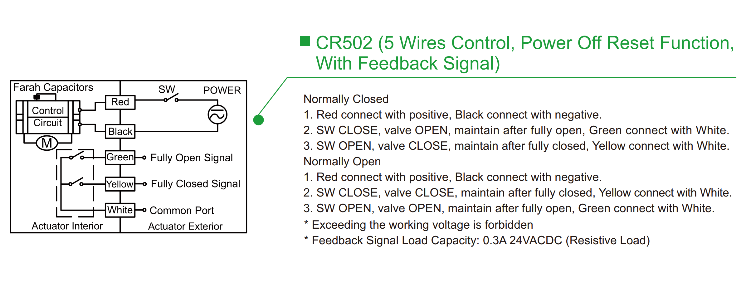
Connect red to the positive supply and black to the negative supply, with the external switch SW in series with the red-wire power circuit. When SW is closed, the actuator closes; after the valve reaches the fully closed position, the internal feedback contact connects yellow to white, indicating the fully closed position. When SW is open, the actuator opens; after the valve reaches the fully open position, the internal feedback contact connects green to white, indicating the fully open position. White is the feedback common and the green, yellow, and white wires must not be treated as ordinary power-input wires.